The Mote Hardware
Hardware vs Software
To really understand robotics you need a broad base of knowledge from many different fields ranging all across the hardware to software spectrum. You have sensors using cutting edge physics and electronics, software running on many different types of constrained environments, and cloud infrastructure keeping it all together.
That can seem daunting at first, but its also its charm. If you love diving deep into a specific branch then there are plenty of niches to become an expert in. If you are more of a generalist, and I count myself in this camp, then there is so much to learn that you will never get bored. No matter where you land though, the boundaries between hardware and software will always be visible.
Now, when it comes to robot tutorials there is a tendency to focus heavily on the hardware leaving the software as an appendix. There are two main reasons for this:
- Unfortunately the cost of hardware required for an autonomous robot can be quite high given a beginners’s budget. To reduce the cost of the hardware, the author either lose some fundamental capability, or they spend more time working around the limitations.
- When starting out there is so much to learn that it can be easier to focus on one thing first. Robotics is enthralling because it is all about the physical system and so hardware often takes the priority. Cheap hardware without software still gives you a robot, but software without hardware isn’t really robotics.
With Mote my goal is to show what a professional robotics software stack looks like, however we can’t just skip the hardware entirely. Instead this post will cover the relatively few pieces of hardware Mote uses, and importantly I’ve tried to cover some of the biggest design decisions I made while choosing them. In every case there was a trade-off and I hope that by the end of this you will understand why a part was chosen, what its benefits are, and what was given up.
Let’s dive in.
Motors
This one is easy to understand - if we want our robot to move, it needs motors. Motors come in many types with many different properties. A motor used for a quadcopter is not the same as one used for a robot arm. But what’s the difference between a £1 motor and a £50 one? What is a servo and how is it different from a motor?
Ok, let’s back up a bit. The first question we always need to ask is what exactly is it we need our robot to do here? Firstly, we want it to move, that’s the obvious one. If we want to turn then we also need to set the relative speeds of the motor on each side. We also want to have some idea of how far we have moved. Breaking these down, we need our motors to:
- Accept speed commands so we can control how the robot moves
- Report how far they have moved so we can keep track of where we are
- Do both accurately enough that we don’t get lost - turning 85 degrees and moving 10m puts you in a different place than turning 90 degrees and moving 10m
Before we go further, it’s worth clarifying that motors alone will never be able to exactly tell you how far the robot has moved. The robot can get caught on things, wheels slip, and general wiggle within the gear train (“backlash”) - all reduce its accuracy. However for all its faults, it’s still our first piece of the puzzle when it comes to tracking our location.
Ok, so you bought the £1 motor, what is it missing? Well it won’t have an encoder, the thing that tracks how far the motor has turned, so we would need to attach one ourselves. It also won’t have anything to control the speed or direction, so we would need to add a driver for that. Finally, we don’t have any way to feed the output movement data back into the control data to ensure our commands are being executed accurately so we will need some sort of controller loop.
What about the £50 motor? Well it likely has an encoder built in and can put out a lot more torque or speed, however it will still need the driver and the controller.
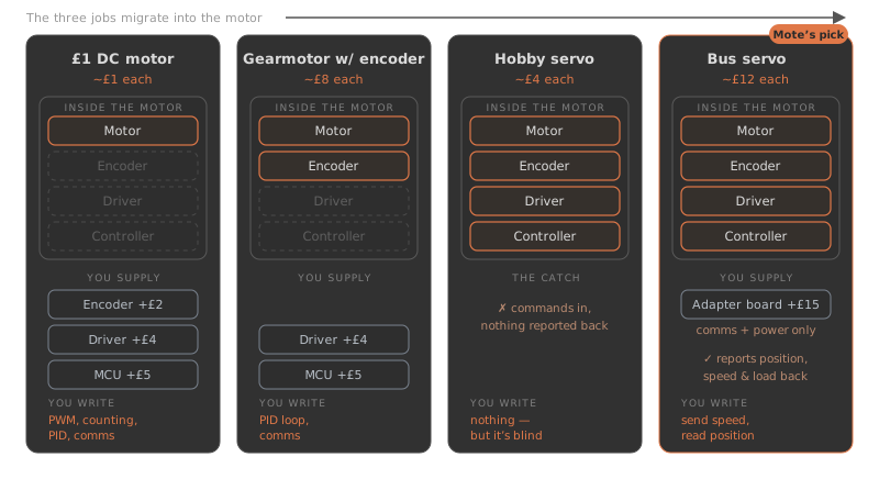
Enter servos. Servos are a special type of motor designed for precise control rather than speed. These have both a controller and an encoder built in which is what allows them to turn to a precise position. Most cheap servos are limited in that they will turn to the desired position, but have no way of feeding that back. This is great for RC applications but not for robotics. Smart (or bus) servos have a digital protocol that allows them to report their position back (along with other data).
Now, smart servos are great, but they are not entirely self-contained. They still need a board that can understand the digital protocol and convert it into something a computer can understand. This board is also responsible for distributing power to the servos. It doesn’t need a controller loop or driver though so it is generally cheaper than a full motor control board needed for motors. On top of this extra board, they have one other big tradeoff: they are really slow. The one we use for Mote has a max speed of about 0.22m/s (at 5V); fine for us but it won’t win any races.
So what does Mote use? Two Feetech STS3215 bus servos (£12 each) plus a £15 adapter board. Checking the list: speed commands over the serial bus (1), position reported back from the built-in magnetic encoder (2), and the control loop closed inside the servo itself (3). That gives us a total cost of around £40.
This compares with two motors with hall encoders (£8 each), an H-bridge driver (£4), and either a microcontroller which you will need to program yourself (a lot of work), or an integrated control board which is expensive (~£80).
So the motors come out at half the cost, but would require us to spend a lot of time looking at soldering, connection diagrams, and programming microcontrollers before we got to the smarts bit. For us the servos are a good balance of cost and get us to the “smart” bit of robotics much quicker.
Battery
Now let’s apply our logic to the battery story. What is it we really need for a robot to power itself? With a limited number of components, we really only need to worry about three things: capacity, size, and connectors.
- capacity - it needs to last a few hours of use - we don’t need a 24/7 operation here
- size - it has to fit in the chassis, close to the ground to keep the centre of mass low
- connectors - it has to connect to all of our other components - primarily the brain (USB-C) and the servo adapter board (5V DC).
There are two main options here - a raw battery pack used for RC vehicles, or a battery pack designed as a phone charger.
Battery packs for RC vehicles tend to be raw LiPo cells that hold a lot of juice but don’t have any smarts to them. They need to be connected through a battery management system that distributes the power out to the various systems as well as monitoring the temperature, voltage, and a few other things to ensure it is operating correctly and safely. Connecting raw DC is a simple solder/connector job, but if your computer wants power from a USB-C port then it gets more complicated.
USB-C battery packs are designed to charge your phone or other electronics quickly with as little fuss as possible. These include a battery management system and avoid some headaches by using a universal connector format (USB!). These make it easy to connect to USB-C devices, and connecting to DC is a simple adaptor (providing you want a standard USB voltage!). The biggest problem however with these is that there are so many options available!
To narrow it down, we need to look back at our requirements. How many connectors, and how much power do we need? Well we will also need one to power our brain which requires 5V at 5A over USB-C. The STS3215 servos we use are rated for 7.4V but work down to ~4.5V (with reduced performance) and require roughly 100mA idle and 500mA while moving.
This gives us a rough estimate for our power draw. Power is just voltage times current, P = VI, so the two servos and the Pi come out as:
That 30W is the worst case, and in most situations it will be far lower than this. A normal battery pack size is about 20Ah (normally displayed as 20,000mAh), which assumes 3.7V:
Minus conversion losses that’s more like 60Wh available, which gives us a runtime of:
So a 20Ah battery pack gives us a minimum 2 hours of active driving with a full CPU load, which is enough for our purposes (back of the napkin, I’ve not measured this yet!).
That gives us the total capacity we are looking for, next we need to consider the connections. The Raspberry Pi is powered via a USB-C port, however it actually wants an off-standard current. Luckily these days a lot of power banks support USB-C PD (Power Delivery) which adds a negotiation step where the voltage and current output are chosen from a range. Without this USB-C is capped at 5V and 3A which would cause the Pi to throttle power to its USB-A ports which are used for the Camera and LIDAR.
For the servo adapter board, we need to supply it with a clean 5V DC connector (barrel jack) with varying current requirements. Normal operation of the servos require 0.5A so 1A between them. This is within the “default” for USB-C so we can just use a cheap adapter to convert the USB-C to barrel jack. Note that we must explicitly use a 5V adapter or it might request a higher voltage and wreck our servos!
In total then we just need two USB-C ports, with one supporting USB-C PD and 25W, the other just needs the 15W baseline. As long as we chose a relatively new pack, we should easily meet both of these requirements.
I’m going to skim over the time I spend deciding on the best size and say I ended up choosing a flat format over a boxier one. The main decider was really just they are more availabile.
To tie it off, the battery pack Mote uses to meet these requirements is the 20Ah pack from UGreen. It has two USB-C output ports, both supporting USB-C PD, and it costs roughly £45.
In the last post we did use a slightly larger 25Ah pack but it didn’t quite fit in the chassis with the cables attached, trading one hour less drive time for no risk of snagging.
The tradeoff here is that automatic recharging is probably out of the question but that seems a fair trade for the simplicity.
LIDAR
Light Detection and Ranging (LIDAR) is a technology that uses laser beams to measure distances. They come in 2D and 3D variants with roughly 500-1000 distance measurements per full rotation (lines per scan) and 10-20 vertical layers (for 3D).
Why do we need a LIDAR? The traditional ROS stack is built upon a costmap (a 2D grid of the area) which is generated by a mapping algorithm. Each cell in a costmap represents its likely “occupancy” - i.e. if it contains an obstacle or not (or unknown). While in theory it is possible to make these maps with other sensors, in practice they always use LIDAR data for its accuracy and reliability.
Once we have a map, the robot can then localise against it - it can see what the map is meant to look like for its current location, and compare it to how it does look. This can be used to correct the localisation drift that comes from using pure wheel odometry. We can also compare consecutive scans to see how the “view” changed and generate a second estimate of our movement.
Finally, and most importantly, LIDAR is used to detect obstacles that move in front of the robot. When people are moving about near the robot, it’s important it can immediately see the person and avoid them or stop. The safety aspect is the main reason they can cost so much. The more expensive LIDARs rotate quicker which reduces the latency between each scan. In turn this allows the robot to react faster. High end ones also have the ability to program an on-board “safety envelope” which can react immediately whenever an obstacle is detected. When the envelope contains a detection, the platform can perform some action almost immediately, either slow or stop.
In our case, we have a fairly easy safety profile. We are very slow (<0.25m/s) and we can stop quickly which means we can get away with a slow refresh rate. We are also very light (<1.3kg) so we don’t need to worry about injuring anyone if we fail to see them.
The price can vary massively depending on speed and features, with traditional brands starting at around £300 with 3D safety rated ones (with the envelope) being upwards of £15,000. Luckily for us the recent developments for robot vacuum cleaners have lowered the entry considerably. The RPLIDAR C1 can be picked up for under £50, scans at 10Hz with 500 lines per scan, and has a ranging resolution of +-30mm. We don’t need anything more than that.
Camera
The biggest downside of 2D LIDARs is that they only capture obstacles on a single plane. Small obstacles on the floor and table tops above are both missed from the scan. If we want to avoid snagging or hitting things, we need a way to see these blind spots.
Most commercial robots will use 3D cameras (RGB-D) for this like the RealSense or OAK-D sensors. These can provide a full, short-range point cloud which can be processed to extract the unseen obstacles. The downside is these start at about £180 while also producing a ton of data that needs processing. This can quickly overload a small computer and also adds more drain on the battery.
On the flip side, a cheap 2D webcam can cost under £15. Recent developments in AI models means that it should be possible to extract similar data from an image. The model Depth Anything can create an estimated depth map from a static image, while many structure-from-motion tools extract depth from a stream of images. Both are very heavy computationally but these can be run on a remote server at the cost of bandwidth and latency. Unlike depth sensors, the stream data in and out of the algorithms is fairly small and so it is at least feasible.
Finally, with a lot of Physical AI research focusing on vision-language-action (VLA) models, we need a camera in any case. If the above algorithms pay off then we save £150, half the price of Mote.
Note I’ve not touched on various camera metrics like resolution, global vs rolling shutter, etc, as realistically even the cheapest cameras have a good enough resolution and the shutter is mostly a reliability measure which we can ignore for now.
Brain
Tying it all together, we need an onboard brain. There are a few different options here depending on your focus but the general trend is simple. More onboard compute means you can do smarter stuff, quicker, but it costs more to purchase and it uses more battery.
At one end of the spectrum you have things like an Arduino which can be really cheap (~£5) but won’t be able to process LIDAR or map, performing more like a dumb edge device that is told what to do. At the other end you can add a full mini-PC on board which will handle all the compute but burn through the battery in no time.
If you want to run AI models on board you might also consider adding some acceleration either by choosing an all-in-one system like the NVIDIA Jetson or adding an acceleration board like the Raspberry Pi Hailo. In both cases these will eat into the battery.
For our use case we want a full Linux system so we need a CPU while also maximising the battery and keeping the cost down. The Raspberry Pi 5 is a good middle ground, although with the cost of RAM it’s still more than I would have liked. The 4GB at £100 should be enough to hold a small-to-medium sized map in memory, although if you plan on mapping a 100k sqm warehouse you might want to opt for more.
As a tradeoff, we will have to perform any learning remotely but as this saves us cash and battery it makes sense for now.
Wrapping up
All in all, the price of Mote comes out to be under £300. I aimed for the cheapest components that give us the capability for full autonomy and interacting with all layers of the robotics stack.
| Component | Price |
|---|---|
| 2x Servos + board | £40 |
| Battery | £45 |
| LIDAR | £50 |
| Camera | £15 |
| Raspberry Pi (4GB) | £100 |
| Cables, screws, etc | ~£20 |
| Total | ~£270 |
With all of that out of the way, hopefully you understand why each of the components of the Mote were chosen along with what the tradeoffs were. My plan is to try and build a small ecosystem around these components to make it as smooth as possible to get started in robotics. If you want to change any of them out for something you already have or for a different use case then hopefully this gives a good base to build upon!
If you have any feedback on the components I chose or any suggestions for additional components please let me know by filing a ticket at github.com/ClachDev/Mote!